1. 调整总线舵机的模式
实现思路:
机械臂包括转台、大臂、小臂三部分,先设置好总线舵机每个ID的工作模式。下图是计划给舵机的各部分设置的ID号:

接下来为各部分设置相应的舵机模式(见下表),并在程序里进行编程设置。

器材准备:
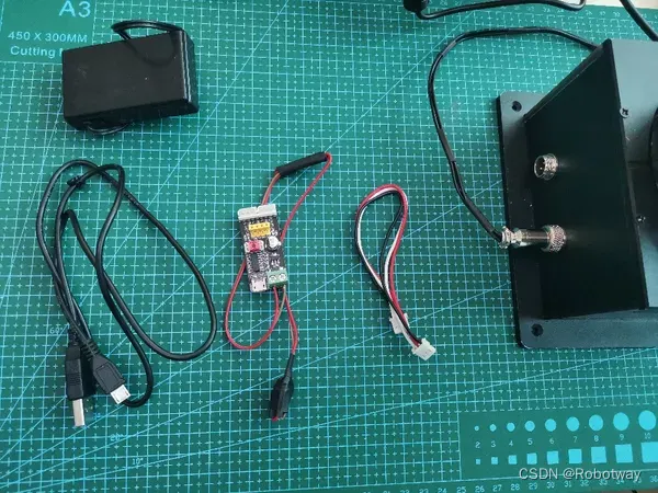
PC机或笔记本电脑(windows操作系统、Arduino IDE)、以及下图所示的其它器材。
1.1修改转台的舵机模式
第一步:按下图所示连接好电路。

第二步:打开文末资料内的”总线舵机ID及模式更改资料\串口调试助手\sscom5.13.1.exe”(如下图所示)。

第三步:选择端口号、波特率,并打开串口。
先在菜单栏:串口设置---打开串口设置,选择端口号、波特率,点击“ok”即可。

接着点击“打开串口”,并点击“扩展”。
人工智能-机器谱robotway-开源-图6" class="J_defImage float_in_img lazyload_transparent" height="90" id="float_img_11077" src="https://img-blog.csdnimg.cn/img_convert/307c46525909d4003437fc85bcce7ee3.png" width="600" />
这里我们已经把命令设置好了,只需要依次点击描红的命令(如下图所示),就可以完成转台模式的设置,即可观察到转台转动到指定角度。
人工智能-机器谱robotway-开源-图7" class="J_defImage float_in_img lazyload_transparent" height="163" id="float_img_11079" src="https://img-blog.csdnimg.cn/img_convert/026c89f551c8cb72c755347879232ac4.png" width="600" />
1.2 修改大臂的舵机模式
第一步:按下图所示把大臂的舵机线与小模块进行电路连接(注意:请先把小模块断电)。

其中,大臂的舵机线如下图所示。
人工智能-机器谱robotway-开源-图9" class="J_defImage float_in_img lazyload_transparent" height="300" id="float_img_11083" src="https://img-blog.csdnimg.cn/img_convert/56effe8b3b654a5a03ec3591d9bc7127.png" width="287" />
第二步:在串口调试助手里,选择端口号、波特率并打开串口。
第三步:依次点击下边描红的命令,就可完成大臂模式的设置,同时可观察到大臂转动。
人工智能-机器谱robotway-开源-图10" class="J_defImage float_in_img lazyload_transparent" height="441" id="float_img_11085" src="https://img-blog.csdnimg.cn/img_convert/5c2bee0791da4f67377327da9fe8e7f6.png" width="600" />
1.3 修改小臂的舵机模式
第一步:按下图所示把小臂的舵机线与小模块进行电路连接(注意:请先把小模块断电)。
人工智能-机器谱robotway-开源-图11" class="J_defImage float_in_img lazyload_transparent" height="376" id="float_img_11087" src="https://img-blog.csdnimg.cn/img_convert/76dfca72e7b61aa563e59788ffd8abc3.png" width="600" />
第二步:在串口调试助手里,选择端口号、波特率并打开串口。
第三步:依次点击下边描红的命令,就可完成小臂模式的设置,同时可观察到小臂转动。
人工智能-机器谱robotway-开源-图12" class="J_defImage float_in_img lazyload_transparent" height="380" id="float_img_11089" src="https://img-blog.csdnimg.cn/img_convert/89d78b72bd67bf339a534e355f01d319.png" width="600" />
这样就完成了总线舵机模式的修改工作。
2. 机械臂运动学控制
控制机械臂最基本的方法是对其建立运动学模型,对于3轴的串联机械臂来说,运动学模型其本质就是给定空间3D坐标,利用运动学算法进行控制。
人工智能-机器谱robotway-开源-图13" class="J_defImage float_in_img lazyload_transparent" height="427" id="float_img_11091" src="https://img-blog.csdnimg.cn/img_convert/577effbb3a1abbf37bf9101519807e8a.png" width="600" />
2.1分析-串联的运动学
串联的运动学有两种:一种是正运动学,一种是逆运动学。
串联的正运动学,简单来说是指确定每个关节舵机转动的角度,从而确定端点位置。这种方法在调试时对于少量自由度的机械臂比较实用,但是当自由度增加时,调试复杂程度也会随之增加。比如下方这个3自由度(不含执行器),我们只需要确定其3个关节上的舵机转动角度α,θ,β,即可确定执行端的位置(暂时不考虑臂长的因素)。

串联的逆运动学,简单来说是指确定端点的位置,然后通过算法计算出各关节需要转动的角度,自动调整到合适的位置。结合本项目中的3轴机械臂(见下图),我们将采用逆运动学算法进行设计,控制运动。

2.2设计-逆运动学算法
这里给大家介绍一种3自由度(不含执行器)逆运动学算法。
为方便大家的理解,算法总共分为5步:第一步为建立空间坐标系;第二步、第三步为简化模型运动学计算;第四步为末端坐标变换的补偿计算;第五步为总体总结。
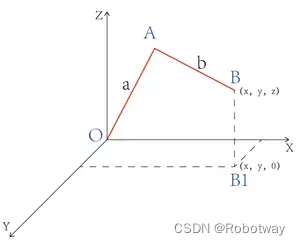
第一步:将以转台旋转中心为原点建立空间坐标系如下:
人工智能-机器谱robotway-开源-图16" class="J_defImage float_in_img lazyload_transparent" height="305" id="float_img_11097" src="https://img-blog.csdnimg.cn/img_convert/6a8ca8af73e3c0589023d99dfa541c84.png" width="600" />
从上图可知:O点为转台旋转轴和大臂旋转轴的交点,A点为大臂的末端,C点为小臂的旋转中心,AC方向为小臂的旋转轴,B点为小臂的末端。
第二步:为了方便计算,我们这里将AC段压缩为0,这样可以简化模型如下:
人工智能-机器谱robotway-开源-图17" class="J_defImage float_in_img lazyload_transparent" height="324" id="float_img_11099" src="https://img-blog.csdnimg.cn/img_convert/8ce5b61fbdc59d2ef0bd5565d23f0eff.png" width="600" />
关于AC段运动的计算,我们在后面的步骤中通过简单的坐标变化进行计算。
第三步:进行简化模型的运动学计算。通过前面的了解,我们知道逆运动是通过坐标来计算出各个关节转动的角度。这里我们可以通过以下步骤建立几何模型和建立运动学算法:
① 将末端B点坐标设置为(x,y,z),作B点在xy平面的投影B1(x,y,0),如下所示:
② 计算转台旋转角度与末端坐标的关系。作O点到B1点的辅助线OB1(下图中两点距离为d),则OB1为OA和AB在xy平面的投影。这里我们假设OX为转台的初始角度,则∠XOB(即图中α)为转台旋转角度,如下所示:

则通过三角函数可得出以下关系:
公式1:
人工智能-机器谱robotway-开源-图20" class="J_defImage float_in_img lazyload_transparent" height="52" id="float_img_11106" src="https://img-blog.csdnimg.cn/img_convert/953587b2e85b437ef569fe3edc8a9b3b.png" width="87" />
d为OB1,可通过两点距离公式得出如下关系:
公式2:
人工智能-机器谱robotway-开源-图21" class="J_defImage float_in_img lazyload_transparent" height="31" id="float_img_11109" src="https://img-blog.csdnimg.cn/img_convert/b82f9b0d8ecff5a9e1cc7efb2c7f58a2.png" width="104" />
将“公式1”与“公式2”结合,可得转台旋转角度α与末端坐标的关系如下:
公式3:
人工智能-机器谱robotway-开源-图22" class="J_defImage float_in_img lazyload_transparent" height="57" id="float_img_11112" src="https://img-blog.csdnimg.cn/img_convert/87c4ea8cea77af7e98655a962b92ed18.png" width="137" />
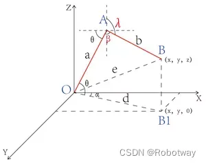
③ 计算大臂和小臂夹角与坐标之间的关系。作O点和B点之间的辅助线OB(图中两点距离为e),则可知∠OAB(即图中β)为大臂小臂的夹角,如下所示:
人工智能-机器谱robotway-开源-图23" class="J_defImage float_in_img lazyload_transparent" height="238" id="float_img_11114" src="https://img-blog.csdnimg.cn/img_convert/2d066101af94015707c6d0f8b88ff5b2.png" width="300" />
从图示关系中,利用三角函数可得以下关系:
公式4:
人工智能-机器谱robotway-开源-图24" class="J_defImage float_in_img lazyload_transparent" height="56" id="float_img_11117" src="https://img-blog.csdnimg.cn/img_convert/8be44934f36ccdcf5cb2a8ac5953f394.png" width="176" />
上式中注意a,b分别为大臂和小臂的长度,可通过实际的进行测量,为已知量;
其中e可根据空间两点距离公式可得:
其中e可根据空间两点距离公式可得:
公式5:
人工智能-机器谱robotway-开源-图25" class="J_defImage float_in_img lazyload_transparent" height="37" id="float_img_11120" src="https://img-blog.csdnimg.cn/img_convert/1a24e48050996fe84e30605712e309e5.png" width="157" />
将“公式4”与“公式5”结合可得大小臂夹角β与末端坐标之间的关系如下:
公式6:
人工智能-机器谱robotway-开源-图26" class="J_defImage float_in_img lazyload_transparent" height="57" id="float_img_11123" src="https://img-blog.csdnimg.cn/img_convert/511ce81aaaf28c4f38ee186f77777d76.png" width="280" />
④ 计算大臂旋转角度与末端坐标之间的关系。从图中可知∠AOB1(即图中θ)为大臂旋转角度:
人工智能-机器谱robotway-开源-图27" class="J_defImage float_in_img lazyload_transparent" height="239" id="float_img_11125" src="https://img-blog.csdnimg.cn/img_convert/6b36601bf1d41f20f0d486213ca841aa.png" width="300" />
如图所示可得以下关系:
公式7:
人工智能-机器谱robotway-开源-图28" class="J_defImage float_in_img lazyload_transparent" height="29" id="float_img_11128" src="https://img-blog.csdnimg.cn/img_convert/c0c872bf915f39b6c751c6d85b916d01.png" width="172" />
其中∠AOB在△AOB中利用三角函数求出:
公式8:
人工智能-机器谱robotway-开源-图29" class="J_defImage float_in_img lazyload_transparent" height="56" id="float_img_11131" src="https://img-blog.csdnimg.cn/img_convert/76f919388a034828f78292ad76404dc1.png" width="279" />
其中e的值可通过“公式5”得出;
“公式7”的∠AOB1在△OBB1用三角函数求出:
公式9:
人工智能-机器谱robotway-开源-图30" class="J_defImage float_in_img lazyload_transparent" height="56" id="float_img_11134" src="https://img-blog.csdnimg.cn/img_convert/3bb14339d0a1778c68af0092cde69980.png" width="288" />
其中z为BB1长度;
人工智能-机器谱robotway-开源-图31" class="J_defImage float_in_img lazyload_transparent" height="31" id="float_img_11136" src="https://img-blog.csdnimg.cn/img_convert/7b51921f76127187616f20ec74606ef9.png" width="141" />
综上“公式7”、“公式8”、“公式9”可得大臂转动角度θ与末端坐标关系:
公式10:
人工智能-机器谱robotway-开源-图32" class="J_defImage float_in_img lazyload_transparent" height="56" id="float_img_11139" src="https://img-blog.csdnimg.cn/img_convert/c30b1041ca10d6823c6aee7d20ceb6b3.png" width="439" />
⑤ 接下来计算小臂转动角度与末端坐标之间的关系。求小臂转动角度,我们需要先来看下小臂的0°所在位置,如下所示:
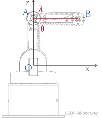
由上图可知,复位时大臂与小臂夹角θ=90°;而实际的小臂初始角度为Z轴正方向,则此时小臂转动角度λ=90°。那么进行运动后,可如下图所示得出小臂转动与末端坐标之间的关系:
如图可知:
人工智能-机器谱robotway-开源-图36" class="J_defImage float_in_img lazyload_transparent" height="27" id="float_img_11145" src="https://img-blog.csdnimg.cn/img_convert/e7d110918dfd23b22bcccc726466e43f.png" width="147" />
其中θ为大臂角度,β关系满足
人工智能-机器谱robotway-开源-图37" class="J_defImage float_in_img lazyload_transparent" height="57" id="float_img_11147" src="https://img-blog.csdnimg.cn/img_convert/de4e9152ff17bc5e65ca93c02d362c6e.png" width="280" />
图中θ为大臂转动角度,图中进行了一个简单的几何关系变化。
最后得到简化模型的运动算法:
转台:
人工智能-机器谱robotway-开源-图38" class="J_defImage float_in_img lazyload_transparent" height="57" id="float_img_11150" src="https://img-blog.csdnimg.cn/img_convert/0f506994ffc2f6cc9b97546be48aecae.png" width="137" />
大臂:
人工智能-机器谱robotway-开源-图39" class="J_defImage float_in_img lazyload_transparent" height="56" id="float_img_11152" src="https://img-blog.csdnimg.cn/img_convert/261e7c5b428b85014047affb8101ec2b.png" width="439" />
人工智能-机器谱robotway-开源-图40" class="J_defImage float_in_img lazyload_transparent" height="31" id="float_img_11153" src="https://img-blog.csdnimg.cn/img_convert/174e534361f11fc18dae74aab9795a7e.png" width="141" />
小臂:
人工智能-机器谱robotway-开源-图41" class="J_defImage float_in_img lazyload_transparent" height="27" id="float_img_11155" src="https://img-blog.csdnimg.cn/img_convert/1a980f24199945db494362f933dbb06d.png" width="147" />
其中θ为大臂角度,β关系满足
人工智能-机器谱robotway-开源-图42" class="J_defImage float_in_img lazyload_transparent" height="57" id="float_img_11157" src="https://img-blog.csdnimg.cn/img_convert/67d81b406ad2c897834bbb9e2f571f29.png" width="280" />
注意:a为大臂长度,b为小臂长度,可通过利用配套游标卡尺测量得出;x,y,z为末端需要达到的实际坐标值。
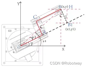
第四步:接下来计算AC段在运动过程中对各关节角度的影响,这里采用一种利用坐标变化的补偿计算。
这里我们先来说下补偿计算的作用。在第二步中我们说到第三步的算法是将AC段压缩为0进行的计算,那么我们在第三步中利用真实的坐标点来计算各关节角度将会有一定的误差。补偿算法就是将实际的坐标转化为与第三步中所得算法一致的坐标,得出变换后的坐标之后,在带入到第三步的算法中进行计算,这样就可以获得准确的各个关节转动的角度。接下来我们详细了解一下具体的计算:
① 我们先在xy平面进行投影,如下所示:
人工智能-机器谱robotway-开源-图43" class="J_defImage float_in_img lazyload_transparent" height="279" id="float_img_11159" src="https://img-blog.csdnimg.cn/img_convert/e6791c2973d3de73a9471ab4485b6cd0.png" width="300" />
图中0A为大臂,AC为大臂末端与小臂旋转中心的间距,CB为小臂;末端点B坐标为(x,y)。
② 为方便计算,作OA延长线AB1,且作B点在该延长线的垂线BB1,相交于点B1,设B1坐标为(x1,y1);
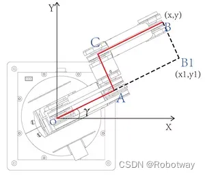
则从图中可知,转台转动角度为γ(这里默认OX为转台初始位置,因为我们这里通过坐标点求角度,所以γ为未知量);
③ 如下图所示作辅助线,B1点、B点作x轴平行线,且B1点作与B点平行线的垂线,如下所示:

通过平行线定理和余角定理可得:
公式11:∠B1=γ;
④ 接下来作连接OB、及B点在X轴垂线的辅助线,计算转台转动角度,如下图所示:
人工智能-机器谱robotway-开源-图46" class="J_defImage float_in_img lazyload_transparent" height="237" id="float_img_11165" src="https://img-blog.csdnimg.cn/img_convert/3dc3fe67730c7560e3b5fab1af5d2a51.png" width="300" />
图中c为大臂末端和小臂旋转中心间距,可通过配套游标卡尺测量,为已知量;
从图中可得:
公式12:
人工智能-机器谱robotway-开源-图47" class="J_defImage float_in_img lazyload_transparent" height="29" id="float_img_11167" src="https://img-blog.csdnimg.cn/img_convert/ef8220ce45b2503bc347048b61d556c5.png" width="97" />
依余弦定理可得:
公式13:
人工智能-机器谱robotway-开源-图48" class="J_defImage float_in_img lazyload_transparent" height="52" id="float_img_11172" src="https://img-blog.csdnimg.cn/img_convert/18ce8981ccba8fa7e65f4d99c74b6c78.png" width="96" />
在△BOB1中,依余弦定理可得:
公式14:
人工智能-机器谱robotway-开源-图49" class="J_defImage float_in_img lazyload_transparent" height="52" id="float_img_11175" src="https://img-blog.csdnimg.cn/img_convert/03f7ca04e124cba2c1b51dd3231cc1d4.png" width="107" />
其中OB依两点距离公式可得:
公式15:
人工智能-机器谱robotway-开源-图50" class="J_defImage float_in_img lazyload_transparent" height="37" id="float_img_11178" src="https://img-blog.csdnimg.cn/img_convert/eef8262d58043d3c05d79a4836428f76.png" width="134" />
合并“公式14”、“公式15”,可得:
公式16:
人工智能-机器谱robotway-开源-图51" class="J_defImage float_in_img lazyload_transparent" height="62" id="float_img_11181" src="https://img-blog.csdnimg.cn/img_convert/f53e1023cd853b5b77a23c96c967a6f8.png" width="157" />
合并“公式12”、“公式13”、公式16,可计算出γ角度:
公式17:
人工智能-机器谱robotway-开源-图52" class="J_defImage float_in_img lazyload_transparent" height="74" id="float_img_11184" src="https://img-blog.csdnimg.cn/img_convert/54a49f27e79005772f804e574c21b25f.png" width="291" />
⑤ 接下来如下图所示,在△HBB1中,利用三角函数计算出B1(x1,y1):
公式18:
人工智能-机器谱robotway-开源-图54" class="J_defImage float_in_img lazyload_transparent" height="29" id="float_img_11190" src="https://img-blog.csdnimg.cn/img_convert/eba226610661b76fee4ff1a1603122c5.png" width="142" />
公式19:
人工智能-机器谱robotway-开源-图55" class="J_defImage float_in_img lazyload_transparent" height="29" id="float_img_11192" src="https://img-blog.csdnimg.cn/img_convert/13821f941a561337ca440763f0f2f62f.png" width="144" />
⑥ 通过前面的步骤,我们已经计算出第一象限的中的坐标变换,但是在第一象限中的转动范围只有0-90°,实际转动范围是0-180°,所以接下来我们计算第二象限的坐标变换,同前面的步骤,可做如下图:

从图中可知,当位于90°-180°之间时(即图中第二象限),可得转台旋转角度关系如下:
公式20:
人工智能-机器谱robotway-开源-图57" class="J_defImage float_in_img lazyload_transparent" height="29" id="float_img_11197" src="https://img-blog.csdnimg.cn/img_convert/37901e1b70099b003b3bd51a2b2f6a2e.png" width="157" />
公式21:
人工智能-机器谱robotway-开源-图58" class="J_defImage float_in_img lazyload_transparent" height="74" id="float_img_11199" src="https://img-blog.csdnimg.cn/img_convert/84c1c157f0d5a0fc4454cd07f917ff0f.png" width="363" />
通过上面步骤,不难在第二象限中得出B点经过坐标变换后得到的B1坐标关系如下:
公式22:
人工智能-机器谱robotway-开源-图59" class="J_defImage float_in_img lazyload_transparent" height="29" id="float_img_11202" src="https://img-blog.csdnimg.cn/img_convert/040377266c0265eeac59df109afa1368.png" width="310" />
公式23:
人工智能-机器谱robotway-开源-图60" class="J_defImage float_in_img lazyload_transparent" height="29" id="float_img_11204" src="https://img-blog.csdnimg.cn/img_convert/4f30ba7bd282ab99503476956bc036a6.png" width="315" />
⑦ 这里咱们将补充中需要的公式进行总结,如下:
当
人工智能-机器谱robotway-开源-图61" class="J_defImage float_in_img lazyload_transparent" height="52" id="float_img_11207" src="https://img-blog.csdnimg.cn/img_convert/6353488e890ee4e06daf97c0ec3c0bbc.png" width="87" />
人工智能-机器谱robotway-开源-图62" class="J_defImage float_in_img lazyload_transparent" height="64" id="float_img_11208" src="https://img-blog.csdnimg.cn/img_convert/751117de975dfae4ce05e248c7e1481d.png" width="154" />
人工智能-机器谱robotway-开源-图63" class="J_defImage float_in_img lazyload_transparent" height="74" id="float_img_11209" src="https://img-blog.csdnimg.cn/img_convert/6cc44c9ae489d432c79f7adcfa964664.png" width="291" />
当
人工智能-机器谱robotway-开源-图64" class="J_defImage float_in_img lazyload_transparent" height="52" id="float_img_11211" src="https://img-blog.csdnimg.cn/img_convert/de15e2c3a110768d6d0c013c69e8f88a.png" width="89" />
人工智能-机器谱robotway-开源-图65" class="J_defImage float_in_img lazyload_transparent" height="64" id="float_img_11212" src="https://img-blog.csdnimg.cn/img_convert/38cfafc2662b2b6459b734fbb84ae302.png" width="154" />
人工智能-机器谱robotway-开源-图66" class="J_defImage float_in_img lazyload_transparent" height="74" id="float_img_11213" src="https://img-blog.csdnimg.cn/img_convert/5c979b227f83896f96654223a94612c0.png" width="363" />
到这里我们完成了坐标变化的补偿计算。
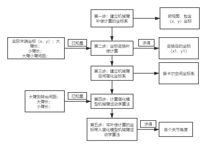
第五步:大家已经了解了运动学计算和补偿计算,那么这两个算法如何搭配使用呢?如何利用算法进行机械臂的逆运动控制呢?这里我们可以通过一个简单的流程来理解。
2.3 实验操作
实现思路:在上位机上通过软件串口监视器,键盘输入机械臂的目标坐标位置,将从起始位置转到目标位置。
如从串口输入坐标(60,60,60),从坐标点(90,90,90)转动到坐标点(60,60,60)。程序中设置起始位置为(90,90,90)。
【备注:上面的坐标点单位为mm】
器材准备:机械臂本体、主控盒、显示屏、键盘、鼠标(如下图所示)

操作步骤:
① 下载文末资料内的参考程序color_experiment_ws\src\InputPoit_By_SerialPort\InputPoit_By_SerialPort.ino:
/*------------------------------------------------------------------------------------

  版权说明:Copyright 2023 Robottime(Beijing) Technology Co., Ltd. All Rights Reserved.

           Distributed under MIT license.See file LICENSE for detail or copy at

           https://opensource.org/licenses/MIT

           by 机器谱 2023-08-10 https://www.robotway.com/

  ------------------------------*/

/*

-----------------------------------------------------------------------------------------------------------------

实验功能:通过arduino的窗口监视器控制机械臂运动。

实验思路:首先编写机械臂三轴运动的逆运动算法(即通过坐标点计算舵机运动的角度);

          之后编写接收arduino串口监视器中的数据,并对该数据进行简单的处理(即数据转换);

          最后,将处理后的数据与机械臂运动算法结合。

实现操作:将该程序下载到arduino开发版,接着按照实验教程连接线路。

        上电后,打开arduino软件的串口监视器,波特率选择115200。

        等待程序运行,直到串口监视器中显示:Please input your poit:

        此时,在串口监视器中输入相应的坐标,观察机械臂是否转到目标点。

        例如:在窗口监视器中输入:60,60,60


实验接线:(主要接线)

        机械臂通信口-------------(机械臂)电控箱

        机械爪(舵机)---------------(执行器)电控箱

        其他线路按照教材图片连接。

Created 2020.7.16     By:Boris.yuan

-----------------------------------------------------------------------------------------------------------------

*/

#include <Arduino.h>

#include <stdio.h>

#include <string.h>

#define CTL_BAUDRATE 115200 //总线舵机波特率

#define SERIAL_PRINTLN Serial1

#define SerialBaudrate 115200

#define Bus_servo_Angle_inits 1500

String receive_string = "";

enum{CATCH=1,REALIZE};

int catch_red_numbers=0;

int catch_blue_numbers=0;

unsigned long old_time = millis();

unsigned long new_time = millis();

unsigned long old_time_blue = millis();

unsigned long new_time_blue = millis();

int value_move[3]={1500,1500,1500};

int last_value[3]={0,0,0};

int poit_sqrt = 0;

int catch_number = 0;

void setup() {

  // put your setup code here, to run once:

  delay(1555);


  Serial.begin(SerialBaudrate);delay(1000);

  SERIAL_PRINTLN.begin(CTL_BAUDRATE);delay(1000);

  Bus_servo_angle_init();delay(3000);

  Pneumatic_raw_init();delay(1000);

  Serial.println("Please input your poit:");

}

void loop() {

  Input_poit_by_Serial();

}

void Input_poit_by_Serial()

{

  while(Serial.available()>0)

  {

    Serial.println("------------------------------------------");

    String receive_string ="";

    String string_division = "";

    int comma_first,comma_second;

    int receive_data[3]={0,0,0};

    int string_test = 0;

    receive_string = Serial.readStringUntil('\n');

    string_test = receive_string.toInt();

    comma_first = receive_string.indexOf(',');

    receive_data[0] = receive_string.substring(0,comma_first).toInt();

    string_division = receive_string.substring(comma_first+1);

    comma_second = string_division.indexOf(',');

    receive_data[1] = string_division.substring(0,comma_second).toInt();

    receive_data[2] = string_division.substring(comma_second+1).toInt();

    poit_sqrt = sqrt(receive_data[0] * receive_data[0] + receive_data[1] * receive_data[1] + receive_data[2]*receive_data[2]);

    Serial.println("The coordinates you entered are:");

    Serial.print("(");Serial.print(receive_string);Serial.println(")");Serial.println(" ");

    if( (comma_first>0) && (comma_second>0) )

    {

       if( (receive_data[0] >220) ||   (receive_data[1] >220) || (receive_data[2] >230) || (poit_sqrt>220) )

       {

          Serial.println("Sorry,The poit is wrong!!!");

       }

      else{

          calculate_postion(receive_data[0],receive_data[1],receive_data[2]);delay(2000);

       }

    }

    else{

          Serial.println("Sorry,The poit is wrong!!!");

    }Serial.println(" ");

  }

}
② 打开串口,选择好波特率和结束符(如下图所示)。

输入机械臂的目标坐标点,查看返回的结果值。【提示:坐标点的范围为0-220】
③ 现在希望机械臂转动到空间位置点(60,60,60),具体的操步骤如下(注意坐标间隔用英文字符“,”,最后一个坐标没有字符):

点击“发送”后,可以观察到机械臂从原位置转动到目标位置点,同时串口显示目标位置,如下图所示:

当然大家也可以尝试让机械臂转动到(80,80,80),看看效果。
3. 机械臂气动搬运
实现思路:利用串联机械臂的逆运动学算法,实现机械臂的气动搬运。实验场景如下图所示,其中两个物块代表所需要搬运的物品。
人工智能-机器谱robotway-开源-图71" class="J_defImage float_in_img lazyload_transparent" height="300" id="float_img_11230" src="https://img-blog.csdnimg.cn/img_convert/fd1e2e412ab1a607b9182a62770645bc.png" width="300" />
操作步骤:
① 下载文末资料内的参考程序color_experiment_ws\src\Pneumatic_manipulator_handling\Pneumatic_manipulator_handling.ino:
/*------------------------------------------------------------------------------------
  版权说明:Copyright 2023 Robottime(Beijing) Technology Co., Ltd. All Rights Reserved.
           Distributed under MIT license.See file LICENSE for detail or copy at
           https://opensource.org/licenses/MIT
           by 机器谱 2023-08-10 https://www.robotway.com/
  ------------------------------*/
/*
-----------------------------------------------------------------------------------------------------------------
实验功能:实现气动搬运物体(抓取两个物体,并放置两个物体)。

实验思路:通过三自由度机械臂算法求出机械臂的逆运动算法(通过坐标点计算出机械臂转动角度),接着
                结合气动吸盘,规划机械臂运动路径(即添加坐标点),将物块抓取并搬运到指定目标点。搬运
                结束后,在打开的窗口中可自行输入机械臂要要运行的轨迹点坐标。

实验接线:(主要接线)
          机械臂通信口-------------(机械臂)电控箱
          气动机械臂---------------(执行器)电控箱
          其他线路按照教材图片连接。
Created 2020.7.16     By:Boris.yuan
-----------------------------------------------------------------------------------------------------------------
*/

#include <Arduino.h>
#include <stdio.h>
#include <string.h>

#define CTL_BAUDRATE 115200 //总线舵机波特率
#define SERIAL_PRINTLN Serial1
#define SerialBaudrate 115200
#define Bus_servo_Angle_inits 1500

String receive_string = "";
enum{CATCH=1,REALIZE};
int catch_red_numbers=0;
int catch_blue_numbers=0;
unsigned long old_time = millis();
unsigned long new_time = millis();
unsigned long old_time_blue = millis();
unsigned long new_time_blue = millis();

int value_move[3]={1500,1500,1500};
int last_value[3]={0,0,0};
int poit_sqrt = 0;
int catch_number = 0;
void setup() {
  // put your setup code here, to run once:
  delay(1555);
  Serial.begin(SerialBaudrate);delay(1000);
  SERIAL_PRINTLN.begin(CTL_BAUDRATE);delay(1000);
  Bus_servo_angle_init();delay(3000);
  Pneumatic_raw_init();delay(1000);
}


void loop() {
  raw_translation();
  delay(8000);
}


void raw_translation()
{
  //catch the first sth
  calculate_postion(60,130,40);delay(3000);
  catch_and_realize_something(0);delay(3000);//catch
  calculate_postion(60,110,80);delay(3000);
  calculate_postion(-120,110,80);delay(3000);
  calculate_postion(-120,130,2);delay(3000);
  catch_and_realize_something(1);delay(3000);//relize
  calculate_postion(-120,130,70);delay(3000);
  calculate_postion(-100,90,70);delay(3000);

  //catch the second sth
  calculate_postion(60,100,70);delay(3000);
  calculate_postion(60,130,10);delay(3000);//down
  catch_and_realize_something(0);delay(3000);//catch
  calculate_postion(60,110,80);delay(3000);
  calculate_postion(-120,110,80);delay(3000);
  calculate_postion(-120,130,37);delay(3000);
  catch_and_realize_something(1);delay(3000);//relize
  calculate_postion(-120,130,70);delay(3000);
  calculate_postion(-100,90,70);delay(3000);
  Bus_servo_angle_init();delay(2000);
  delay(1000);
}
② 程序下载完成后,观察气动搬运效果。正常情况下机械臂会先搬运上边的物块,放置在一侧;接着再搬运下边的物块,并把其放置在刚才的第一个物块上。
4. 机械臂手爪搬运
实现思路:利用串联机械臂的逆运动学算法,实现机械手爪搬运两个物块。实验场景如下图所示,其中两个物块代表所需要搬运的物品。

操作步骤:
① 下载文末资料内的参考程序color_experiment_ws\src\Manipulator_handling\Manipulator_handling.ino:
/*------------------------------------------------------------------------------------
   版权说明:Copyright 2023 Robottime(Beijing) Technology Co., Ltd. All Rights Reserved.
           Distributed under MIT license.See file LICENSE for detail or copy at
           https://opensource.org/licenses/MIT
           by 机器谱 2023-08-10 https://www.robotway.com/
   ------------------------------*/
/*
-----------------------------------------------------------------------------------------------------------------
实验功能:实现气动搬运物体(抓取两个物体,并放置两个物体)。

实验思路:通过三自由度机械臂算法求出机械臂的逆运动算法(通过坐标点计算出机械臂转动角度),接着
                结合气动吸盘,规划机械臂运动路径(即添加坐标点),将物块抓取并搬运到指定目标点。搬运
                结束后,在打开的窗口中可自行输入机械臂要要运行的轨迹点坐标。

实验接线:(主要接线)
          机械臂通信口-------------(机械臂)电控箱
          气动机械臂---------------(执行器)电控箱
          其他线路按照教材图片连接。
Created 2020.7.16     By:Boris.yuan
-----------------------------------------------------------------------------------------------------------------
*/

#include <Arduino.h>
#include <stdio.h>
#include <string.h>

#define CTL_BAUDRATE 115200 //总线舵机波特率
#define SERIAL_PRINTLN Serial1
#define SerialBaudrate 115200
#define Bus_servo_Angle_inits 1500

String receive_string = "";
enum{CATCH=1,REALIZE};
int catch_red_numbers=0;
int catch_blue_numbers=0;
unsigned long old_time = millis();
unsigned long new_time = millis();
unsigned long old_time_blue = millis();
unsigned long new_time_blue = millis();

int value_move[3]={1500,1500,1500};
int last_value[3]={0,0,0};
int poit_sqrt = 0;
int catch_number = 0;
void setup() {
   // put your setup code here, to run once:
   delay(1555);
   Serial.begin(SerialBaudrate);delay(1000);
   SERIAL_PRINTLN.begin(CTL_BAUDRATE);delay(1000);
   Bus_servo_angle_init();delay(3000);
   Pneumatic_raw_init();delay(1000);
}


void loop() {
   raw_translation();
   delay(8000);
}


void raw_translation()
{
   //catch the first sth
   calculate_postion(60,130,40);delay(3000);
   catch_and_realize_something(0);delay(3000);//catch
   calculate_postion(60,110,80);delay(3000);
   calculate_postion(-120,110,80);delay(3000);
   calculate_postion(-120,130,2);delay(3000);
   catch_and_realize_something(1);delay(3000);//relize
   calculate_postion(-120,130,70);delay(3000);
   calculate_postion(-100,90,70);delay(3000);

   //catch the second sth
   calculate_postion(60,100,70);delay(3000);
   calculate_postion(60,130,10);delay(3000);//down
   catch_and_realize_something(0);delay(3000);//catch
   calculate_postion(60,110,80);delay(3000);
   calculate_postion(-120,110,80);delay(3000);
   calculate_postion(-120,130,37);delay(3000);
   catch_and_realize_something(1);delay(3000);//relize
   calculate_postion(-120,130,70);delay(3000);
   calculate_postion(-100,90,70);delay(3000);
   Bus_servo_angle_init();delay(2000);
   delay(1000);
}
② 程序下载完成后,观察搬运效果。
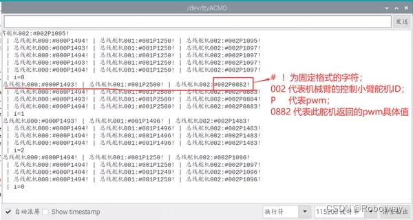
5. 机械臂位置反馈
实现思路:让机械臂做3组动作,然后返回其相应的舵机的pwm值。其中机械臂包括转台、大臂、小臂三部分,实验中将分别返回控制其三部分的舵机Pwm值。
人工智能-机器谱robotway-开源-图73" class="J_defImage float_in_img lazyload_transparent" height="408" id="float_img_11243" src="https://img-blog.csdnimg.cn/img_convert/42e8ef7c3a9aea0a12837d0b1d053ce0.png" width="600" />
每个总线舵机的pwm范围为:500~2500,每个舵机模式为:180度。
所以舵机的实际角度与pwm映射关系为:angle=map(要输入的pwm值:500,2500,0,180)。明白了此原理后,接下来就可以实际操作了。
操作步骤:
① 下载文末资料内的参考程序color_experiment_ws\src\Get_BusServo_Current_Angle\Get_BusServo_Current_Angle.ino:
/*------------------------------------------------------------------------------------
  版权说明:Copyright 2023 Robottime(Beijing) Technology Co., Ltd. All Rights Reserved.
           Distributed under MIT license.See file LICENSE for detail or copy at
           https://opensource.org/licenses/MIT
           by 机器谱 2023-08-10 https://www.robotway.com/
  ------------------------------*/
/*
-----------------------------------------------------------------------------------------------------------------
实验功能:在串口监视器中查看舵机当前转动的角度。

实验思路:首先编写驱动总线舵机驱动程序,之后,编写接收串口监视器数据的程序,接着将
        串口监视器接收的数据进行简单的处理,最后,将处理后的数据与机械臂各部位结合。

实验操作:将该例程下载到arduino开发版,接着按照实验教程连接线路,完成后,打开arduino
        的串口监视器,结合总线舵机使用教程,观察串口监视器中的数据是否与总线舵机教程相符。
        例如串口监视器输出的:总线舵机000:#000P1114!表示的意思是:
                              地址为000的总线舵机(即转台)当前的pwm值为1114(即55度)。
                              度数angle与pwm的关系式为: angle = map(pwm,500,2500,0,180)
实验接线:(主要接线)
          机械臂通信口-------------(机械臂)电控箱
          其他线路按照教材图片连接。
Created 2020.7.16     By:Boris.yuan
-----------------------------------------------------------------------------------------------------------------
*/


#include <stdio.h>
#include <string.h>

#define CTL_BAUDRATE 115200 //总线舵机波特率
#define SERIAL_PRINTLN Serial1
#define SerialBaudrate 115200
#define Bus_servo_Angle_inits 1500

String receive_string="";
int value_move[3]={1500,1500,1500};
int last_value[3]={0,0,0};

void setup() {
  // put your setup code here, to run once:
  delay(1100);
  Serial.begin(SerialBaudrate);
  SERIAL_PRINTLN.begin(CTL_BAUDRATE);
  Serial.println("Start!");
  Bus_servo_angle_init();delay(2000);
  int ss = map(1114,500,2500,0,180);
  Serial.println(ss);
}


void loop() {

  for(int i=0;i<3;i++)
  {
    arm_action_test(i);
    for(int j=0;j<3;j++){
      Read_get_busservo_angle_current(j);
      delay(1000);
    }
    delay(5000);
  }
}
② 打开串口,查看返回的结果值(如下图所示)。
程序源代码及总线舵机ID及模式更改资料下载地址详见 桌面级机械臂-运动控制